Reflections in High-Frequency PCB Designs
High-frequency PCB designs require careful consideration of impedance, signal propagation, and electromagnetic interference (EMI). Typical conventional FR-4 substrates exhibit significant dielectric losses at higher frequency, so specialized materials are required to support the requirements of high-speed circuit boards. Moreover, the physical layout of components and transmission lines plays an important role in the performance of these high-speed circuits. These considerations can minimize reflections, which are the primary source of noise and interference in high-speed PCBs.
There are multiple PCB manufacturing processes available, and each has its own set of advantages and disadvantages. In general, copper-based PCBs are the most durable and cost-effective, but they may not be suitable for high-frequency applications. In these cases, a high-frequency board requires a special material that can withstand temperature changes and other environmental factors. In addition, it must have low moisture absorption and dimensional stability to prevent deformation during fabrication.
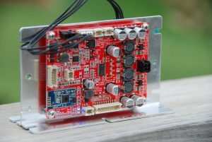
For example, the materials used to make a high frequency pcb should have a similar rate of thermal expansion so that they do not separate from one another when exposed to heat. They should also have good thermal conductivity, chemical resistance, and strength.
How to Minimize Reflections in High-Frequency PCB Designs
The materials used in a high-frequency pcb must also have a stable dielectric constant and provide good heat dissipation. These factors can influence the reliability of a high-frequency pcb and reduce its total cost. In addition, they must be able to resist corrosion and provide adequate insulation.
The physical layout of a high-speed PCB is critical in minimizing interference between traces. The layout should follow the 3W rule, which states that a signal line should be separated by three times its width to avoid interference. This is because high-speed signals produce high radiation, and if they share a path, it can cause EMI.
Another way to minimize reflections is by properly matching trace impedance and terminating the lines. The ideal impedance for a signal line is 50 ohms, which matches cable impedance and provides a good tradeoff between conduction losses and reflections. However, this can only be achieved with the help of simulation, which can identify and mitigate impedance discontinuities at layer transitions and point-to-point connections.
In addition, it is crucial to use the correct terminations for a high-frequency PCB design. The wrong termination can result in ringing and noise in the signal waveform, which can lead to failures. This is why it’s best to consult a reputable PCB manufacturer to ensure that your design meets all the necessary specifications for a high-speed circuit board.
A PCB manufacturer can help you determine the voltage and power demands of your integrated circuits, whether you’ll be dividing any ground or signal planes, and which materials to use. They can also help you choose the correct routing scheme and use the latest technology to minimize reflections. This will ensure that your product performs optimally. The manufacturer will also ensure that your high-frequency PCBs are free of defects, which is vital for accurate data transmission.